Irrigation Design Tip: Sizing Pipe
Simple steps to correctly size pipe for your project
We will use the principles of hydraulics to size all the components in the system and to ensure adequate flow and pressure to properly operate all the sprinklers on the project.
In the Understanding Basic Hydraulics section of the Irrigation Design Manual, the 5 ft/s (1,5 m/s) velocity safety limit for pipe is discussed. To review, at 5 ft/s (1,5 m/s), the speed of the water in the pipe is less likely to cause damaging surge pressures. The second reason for holding velocity at or below 5 ft/s (1,5 m/s) is that friction losses increase dramatically as more water is being forced through the pipe at higher speeds. The simplest way to keep these factors where they can be controlled is to size the pipe in an irrigation plan using the 5 ft/s (1,5 m/s) method.
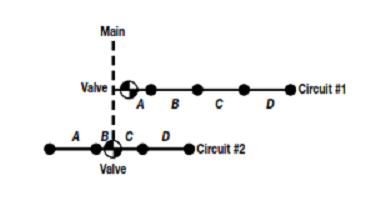
First, let's look at two typical valve circuits that have not yet had their lateral pipe sizes specified.
Each circuit has four, medium-sized rotor pop-up sprinklers that throw 47 ft (14,33 m) at 55 psi (3,8 bar), and each require 9.8 gpm (2,22 m3 /h or 0,62 L/s). They spaced them in an equilateral triangular pattern at 50% spacing, but has chosen a different lateral pipe configuration for each circuit. For reference, the various pipe sections of each lateral have an identification letter.
The water supply must reach the furthest sprinkler out with a minimum of 55 psi (3,8 bar) to get the desired performance at the selected spacing. Before sizing the lateral pipes, we to select what type of pipe to specify. In this case, a medium strength pipe, Class 200 PVC is chosen because it has good flow characteristics
Using the Class 200 PVC pipe chart, we ready to begin sizing the lateral pipe. Pipe sizing for a sprinkler lateral is done in reverse.
The first pipe to be sized is the pipe reach supplying the last or furthest sprinkler from the valve.
When the size has been established for that reach, the next reach in, supplying the last two sprinklers, should be sized. This process continues, moving backward (or upstream) from the last sprinkler, and toward the valve. The route this sizing procedure follows along the various pipes in the circuit is called the critical circuit length. This route is defined as the longest path in the circuit that the water will have to travel.
The critical length may also be described as the length between the valve and the most distal sprinkler.
Circuit #1 the critical circuit length for this lateral includes all the pipe sections, section “A” through section “D.” The longest path from the valve to the most distal sprinkler is through all the lateral pipes.
On circuit #2 the lateral is split with the valve in the center of the circuit. The circuit is not split exactly in half. If it was, we could use either side of the circuit as the critical path. There is a slightly longer water path from the valve down through sections “C” and “D” to the furthest sprinkler. Sections “C” and “D,” therefore, make up the critical circuit length for example two.
With the type of pipe selected and the critical lengths determined, we are ready to use the Class 200 PVC pipe chart and the 5 ft/s (1,5 m/s) method to size the lateral lines.
Starting with Circuit #1 with the last sprinkler which requires a flow of 9.8 gpm (2,22 m3/h or 0,62L/s), but the pipe supplying it cannot have a velocity of more than 5 ft/s (1,5 m/s).
Checking the Class 200 PVC pipe chart, we will look for the smallest pipe that will carry 9.8 gpm (2,22 m3/h or 0,62 L/s) without exceeding the5 ft/s (1,5 m/s) limit.
The highest flow for 3/4 in (20 mm) Class 200 PVC pipe before going into the shaded area on the chart is 10 gpm (2,27 m3/h or 0,63 L/s). The flow demand for the sprinkler,9.8 gpm (2,22 m3/h or 0,62 L/s), can be met by the 3/4 in(20 mm) size with a velocity of about 4.7 ft/s (1,43 m/s).
The pipe size for section “D” then is 3/4 in (20 mm).
Working backward toward the valve, section “C” is the next pipe to be sized.
This section supplies two sprinklers, each requiring 9.8 gpm (2,22 m3/h or 0,62 L/s) for a total flow of 19.6 gpm (4,45 m3/h or 1,24 L/s). The pipe chart shows that not only is 3/4 in (20 mm) pipe out of the question, but 1 in (25 mm) pipe is too small also. At nearly 20 gpm (4,54 m3/h or 1,26 L/s), this section of the lateral requires 1-1/4 in (40mm) pipe to support two sprinklers while adhering strictly to the 5 f/s (1,5 m/s) rule. 1-1/4 in (40mm) pipe is selcted for section “C.”
Section “B” supports three sprinklers at 9.8 gpm (2,22 m3/h or 0,62 L/s) each for a total of 29.4 gpm (6,67 m3/h or 1,84L/s). The smallest pipe on the chart that meets the flow needs for the three sprinklers and is within the limit is1-1/2 in (40 mm) pipe. Having sized section “B” at 1-1/2 in(40 mm), the next section is a short one, section “A.”
Section “A” supports all the sprinklers on the lateral line for a total of four sprinklers at 9.8 gpm (2,22 m3/h or 0,62 L/s) each or 39.2 gpm (8,89 m3/h or 2,47 L/s). The chart says 2 in (50 mm) pipe is required for section “A” and this last section is sized accordingly.
The critical path for Circuit #1 has been sized.
Circuit #2 has the same type of sprinklers and the same type of pipe.
Therefore, to support one sprinkler, we know 3/4 in (20 mm) is required for section “D” on this new circuit. Similarly, section “C,” supporting two sprinklers, needs 1-1/4 in (32 mm) pipe. With that decided for Circuit #2, we have completed sizing the critical circuit length.
Here is how the two circuits look:
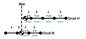
After sizing sections “C” and “D” for Circuit #2, we also know the sizes for sections “A” and “B.” Those two sections are nearly a mirror image of sections “C” and “D,” so “A,” which supports one sprinkler, is 3/4 in (20 mm) and “B,” which supports both sprinklers, will be 1-1/4 in (32 mm).
One of the advantages of splitting a sprinkler circuit is clearly evident in the above example. By splitting Circuit #2 and feeding it from a centrally located valve position, we have eliminated the need for the two larger pipe sizes. In addition to saving the cost of these bigger pipes, the cost of the larger fittings is gone and, if all the circuits of this size were similar, the contractor could standardize the materials inventory for the project. The circuit is also balanced with less pressure variation between sprinklers.
You can read more about this topic and complete more practice excercises using Rain Bird Landscape Irrigation Design Manual.